We have already introduced the clean agent fire suppression system, of which FM200 is one, in Ganjineh Pavan‘s articles. Also, in another article, we examined the FM200 fire suppression system, its benefits and applications, and the method of installing the FM200 fire extinguishing system. Now, in this article from Ganjineh Pavan’s articles, we want to discuss the principles of FM200 extinguishing system design and the critical points related to it.
The FM200 fire extinguishing system, also known as the HFC227ea fire extinguishing system, is one of the most effective clean agent fire extinguishing systems as an alternative to sprinkler systems in environments containing sensitive goods and systems.
As a clean agent fire extinguishing system, FM200 (HFC 227-ea) not only protects rooms from fire damage or spread but, most importantly, equipment that is of high value and critical to business operations and continuity. Fire and protect against damage that a water fire extinguishing system or foam fire extinguishing system may cause.
FM200 system design standard
In the list of NFPA standards of the American Fire Protection Organization, the NFPA 2001 code is assigned to the standard of clean-acting gas fire extinguishing systems, which also includes the design of the FM200 fire extinguishing system.
For the design and installation of the FM200 fire extinguishing system, the NFPA 2001 standard recommends that the system be designed by a qualified fire extinguishing system designer.
In general, the design of the FM200 extinguishing system should include the requirements of NFPA, NFPA 2001, and NFPA 72 and the recommendations of the manufacturer of the equipment used.
Designing the FM200 starts with identifying the type of hazard we are going to protect against, the ambient temperature, and the room altitude.
Once the fire hazard class has been determined, the minimum design concentration can now be determined concerning ambient temperature and room altitude above sea level. Designers should note that any raised floor and enclosure, if not separated by a wall, should be considered protected as defined in NFPA 2001.
Design Range
The design of the FM200 system includes determining the amount of agent, piping layout, pressure drop through piping, and accessories, as well as fixing the location and quantities of discharge nozzles for uniform distribution of the agent throughout the space.
The design of the FM200 system also includes determining the filling density in the operating cylinders to take care of the pressure drop through the system and determine the number of cylinders.
From the number of cylinders, the amount of agent required to flood the entire space is determined independently based on the design concentration of the agent required for the type of fire, the stopping time for fire extinguishing, the additional amount required to take care of leakage, and other issues.
In the design of the FM200 system, the experimental measurement of the pipe and the routing of the pipe with the location of the nozzle are done by the owner or engineer in coordination with other facilities in the space.
To take care of the system pressure drop and create the required pressure in the nozzles, the authorized representative determines the filling density of the agent in the cylinder. They also finalize the number of cylinders based on full density and their standard cylinder size.
Protected areas
Areas to be protected are identified through a fire hazard analysis of zones and related NFPA codes.
Requirements are determined based on the functional importance of the protected system, the extent of damage, fire insurance premiums, etc.
Effective factors in determining the concentration of FM200
Since FM 200 is the most expensive agent in the entire system, careful analysis is required before determining the required concentration and total amount of agent.
In the design of the FM200 extinguishing system, the maximum concentration limit of FM200 is limited by NFPA 2001 due to safety considerations regarding toxic and physical effects on human life.
NFPA 2001 Section a-1-5.1.2 recommends a concentration level below FM 200 in a protected enclosure:
-
- No Observed Adverse Effect Level (NOAEL) – concentration of 9% or less (%V/V)
-
- Lowest observable adverse effect level (LOAEL) – concentration above 10.5% (%V/V).
Use a minimum design concentration of 6.7% for Class A and 7% for Class C, and a minimum of 8.7% for Class B (heptane) or as recommended by the manufacturer for other flammable liquids.
A typical occupied space should have up to 10.5% of the design concentration, while an unoccupied space can exceed this concentration, provided that sufficient time is provided for the evacuation of people, which can be done by setting a countdown timer. Do not exceed the maximum acceptable human exposure time.
Determining the factor value in the design of the FM200 system
In the design of the FM200 fire suppression system, the formula mentioned in paragraph 3.5.1 of NFPA 2001 is used to calculate the initial quantity of the agent requirement:
The description of its parameters is as follows:
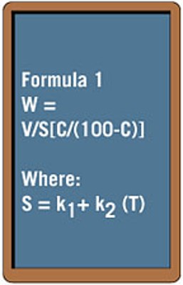
W = weight of clean agent, lb/ft.
T = minimum expected temperature of the protected volume, degrees Fahrenheit.
C = design concentration of FM 200, volume percent.
V = hazard volume, which is the volume of the protected room. Sometimes, the volume occupied by the air conditioning channel inside the room up to the first insulation damper is added to the volume of the room, for example, when the room has a false ceiling and the channel flows in the space above the false ceiling.
S = k1 and k2 (T) is a linear equation determined by least squares curve fitting techniques from data provided by clean agent manufacturers.
k1 and k2 = constants specific to the cleaning agent used (FM 200), whose values should be taken from NFPA 2001 Table 5.1-3-5.1(a).
Determining the temperature of the protected area
Regarding the selection of the temperature inside the protected area in the design of the FM200 extinguishing system, NFPA recommends a minimum predicted temperature. The authorized system designer usually considers the prevailing temperature inside the air-conditioned rooms.
With the lower temperature of the volume to be protected, the need for an increased amount of agent increases. However, under unusual conditions, such as factory maintenance, when the air conditioning system is not working, the indoor temperature may reach the minimum outdoor temperature.
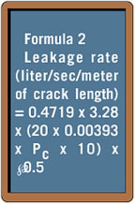
Agent leakage from the enclosure is an important issue in maintaining the desired agent concentration within the enclosure during the holding time required for fire suppression.
The total FM200 piece is discharged in a short period of 10 seconds, suddenly increasing the pressure inside the chamber due to the expansion of the agent. However, a sudden increase in pressure will decrease to normal room pressure in a short period of time at rest. Therefore, there is a possibility of leakage at the time of evacuation as well as at rest due to the heavier mixture of air and agent in the room compared to the outside air.
Expansion factor during discharge
In the design of the FM200 extinguishing system, the leakage caused by the expansion at the time of evacuation is included in Formula 1 in the calculation of the initial factor value in NFPA 2001. FM 200’s sudden expansion on initial discharge is not accounted for in a tight enclosure, which has no large openings that would be difficult to seal.
At rest, due to the difference in density between the air mixture FM 200 inside the room and the air outside the room, the mixture of FM 200 and air leaks out of the room through the leakage zone. According to NFPA recommendations, the height of the room is considered the static head for leakage.
To be more precise, in the design of the FM200 extinguishing system, the amount of leakage is determined by the pressure test of the door fan, according to NFPA 2001. The amount of leakage is estimated based on possible leakage areas, such as leakage from the door gap, damper gap, high floor tiles, etc.
The effect of height in the design of the FM200 system
At higher altitudes, FM 200 expands into a more specific vapor. Designed for sea level, the system produces a higher concentration level at higher altitudes. To correct for higher altitude effects, the factor value is reduced by a factor found in the authorized system designer catalog cuts.
Determining agent hold time
To effectively extinguish the fire, the concentration of the design agent must be maintained inside the room for a period of time called Agent Hold Time. So the holding time is the time required to keep the agent inside the chamber at the desired concentration until the fire is extinguished.
Therefore, it should be noted that in the design of the FM200 extinguishing system to maintain the design concentration until the end of the storage time, the amount of extracting agent in Formula 1 is increased by the amount of expected leakage. To initially discharge a larger amount of agent than the design concentration. This effectively increases the initial agent concentration above the design concentration. However, the initial agent concentration decreases to the design concentration due to agent leakage during the storage period.
Section B-2.7.1.7, NFPA 2001, provides a formula for FM200 fire extinguishing system design to calculate the time required to maintain the descending interface level of the air-agent mixture at or above the height required for the minimum agent concentration in the room.
The NFPA formula for calculating holding time is as follows:
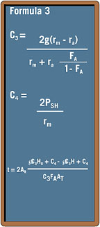
The description of its values is as follows:
t = time in seconds. The downlink enclosure is expected to maintain H for time t. This is the maximum waiting time for a risk.
C3 = constant to simplify the equation.
C4 = constant to simplify the equation.
AR = floor area of the room, in square meters.
AT = total leakage area in square meters.
g = acceleration due to gravity, 9.81 m/s2.
PSH = static pressure during discharge, Pa.
PSH = 0.25 PC, max. See NFPA 2001, Section B-2.5.2.3.
PC = pressure due to the operating column (density difference), Pa.
PC = g H0 (rm – ra). See NFPA 200a, Section B-2.6.1.3.
rm = FM 200, and the density of the air mixture is kg/m3. See NFPA 2001 Section B-2.7.1.4.
ra = air density, kg/m3.
H₀ = ceiling height in meters.
H = height of the interface from the floor, m.
H = H₀ (CF/C). See NFPA 2001, Section B-2.7.1.6.
CF = final agent concentration, 7.44% (assumed, as previously mentioned, to maintain the design concentration to extinguish the fire).
C = initial agent concentration, obtained from the total amount of FM 200 discharged in the volume to be protected. In any case, in the design of the FM200 extinguishing system, it should be considered that the maintenance time should not be less than ten (10) minutes.
Which is a traditional general value for fire extinguishing.
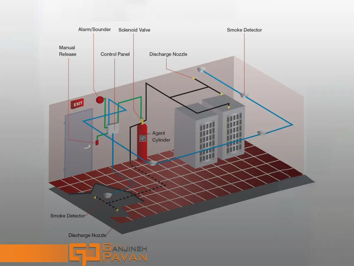
Installation of equipment in the design of the FM200 system
In the design of the FM200 extinguishing system, the installation location of the fire extinguishing and alarm equipment must comply with the relevant standards.
Detectors
The detector spacing shall be the manufacturer’s recommended spacing or as per NFPA 72, taking into account the area covered for weather changes during day and night hours.
This is particularly important in rooms with high air velocities, where the smoke from the fire is diluted before entering the smoke chamber of the detector, thereby reducing its effectiveness.
Advantages
- Widely accessible,
- Quick response time,
- Minimal downtime,
- Requires less agent compared to inert gases, leading to smaller storage needs,
- Easy to install,
- Simple to commission,
- Leaves no residue, keeping sensitive equipment like servers and electronics clean,
- Designed to be safe and non-toxic, ensuring breathable air if people are present when activated.
Disadvantages
- More expensive than wet systems,
- Designed for total flooding applications, leading to full system discharge,
- Enclosures must withstand peak pressures during gas release, potentially necessitating additional structures or pressure relief systems,
- Health and safety considerations during installation,
- Not entirely eco-friendly, contributing to global warming due to the presence of HFCs.
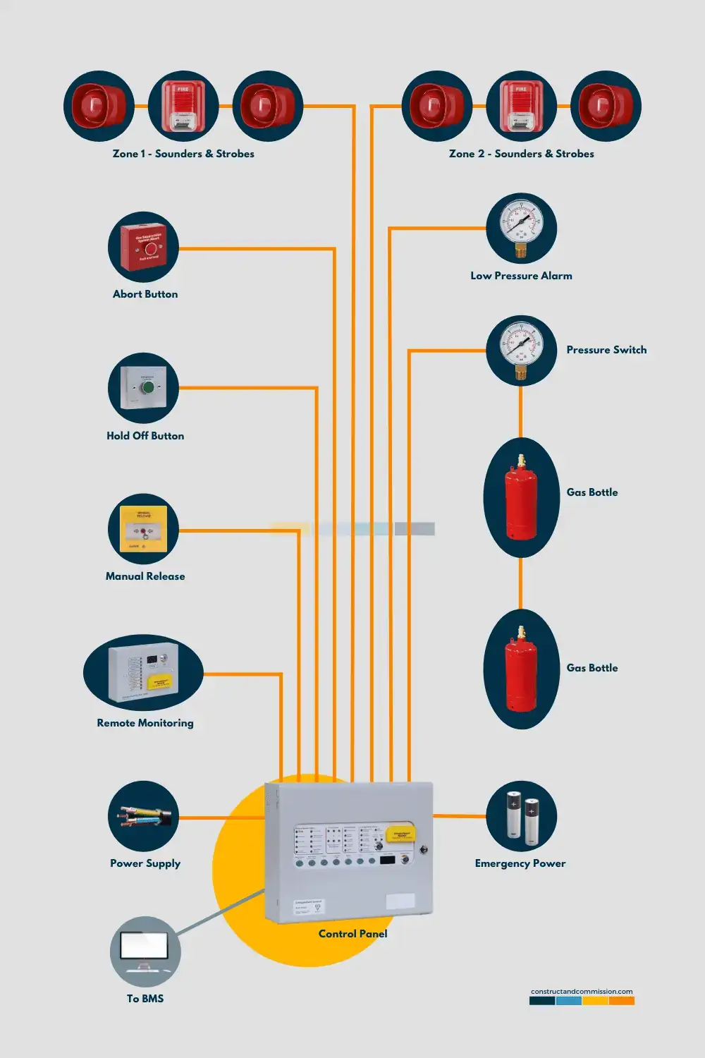
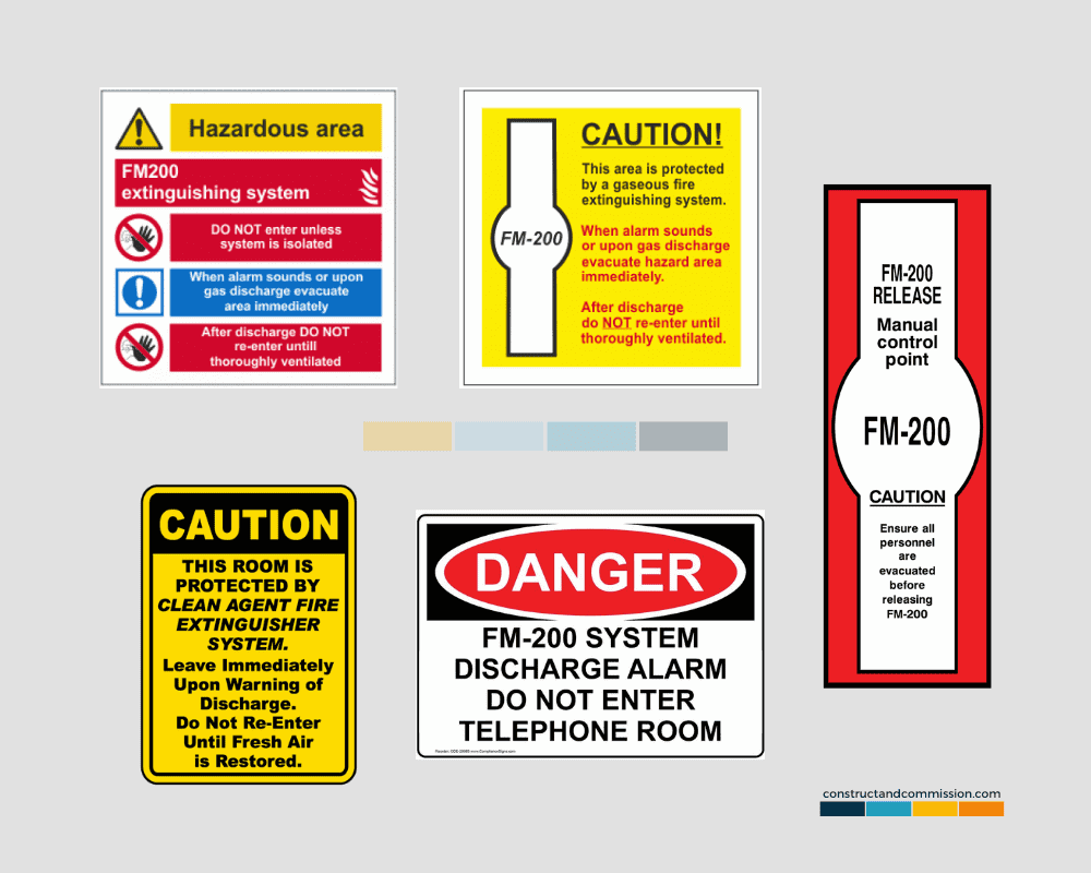
Alarms and sirens
In the design of the FM200 extinguishing system, it is recommended to install a manual cut-off and release switch uniformly. That means you have to put the disconnect switch in the thumb position.
Audio and visual sirens must be installed inside and outside the protected area as per NFPA 2001. The disconnect switch should be located inside the room, while the manual release is located outside.
The location of the control panel in the design of the FM200 fire suppression system
The location of the fire extinguishing control panel should be protected near the entrance door and outside the area. The operating cylinder storage area should have an operating temperature between 20 °C and 54 °C, as recommended by most manufacturers.
In the design of the FM200 extinguishing system, it is recommended that the cylinder be as close as possible to the protected areas or within the manufacturer’s limits. Which is easily identified, especially when hydraulic flow calculations are available.
Conclusion
The design and implementation of the FM200 fire suppression system is a specialized task that requires expertise and adherence to stringent standards.
Ganjineh Pavan consultant, supplier, designer, and implementer of the FM200 extinguishing system
In this article, from Ganjineh Pavan’s articles, we discussed the principles and effective factors in the design of the FM200 extinguishing system. The design of the FM200 fire extinguishing system is a specialized process that must be carried out by a specialized team of qualified companies.
Ganjineh Pavan company, relying on the experience and technical knowledge of specialists, is ready to provide consulting services, receiving representation, supervision, supply, design, and implementation of FM200 fire extinguishing system.
Ganjineh Pavan provides consulting, design, supply, installation and implementation, testing, and maintenance services in the following fields:
- Design and installation of fire alarm system
- Design and installation of fire extinguishing system
- Supply, design, and installation of the F&G system
- Safety equipment and personal protection
- Consulting and obtaining fire department approval for the completion of building work
To receive free advice to improve the safety and financial security of your place of residence and business, contact the expert consultants of Ganjineh Pavan Company now.
References: